| Главная » Статьи » Разное |
The best solution for working with distant correspondents, this application stack (cm . figure 7). A
well-tuned stack, for example, 2 antennas on three elements, even with
short antennas, such as "Robinson" always wins in the long road toward
7-element wave channel . To install the distant relationships are widely used directional antennas that emit most of the energy supplied to them in a given direction . Directional antenna systems allow the creation of radiation at low angles to the horizon . This is of particular importance to the implementation of long-distance relationships . short wave absorption in the ionosphere is small, therefore, the intensity of the reflected rays of her space is very high . Through this whole long-distance relationship at short wavelengths by using spatial beams . weak absorption of the spatial beam in the ionosphere and the phenomenon of multiple reflections allow communication short waves at a distance of thousands of kilometers, with a relatively low power transmitter . primary goal in the design and construction of antennas for telecommunications, is the formation of a narrow beam antenna pattern pressed to the horizon and to ensure low losses in the antenna system itself, that is a good efficiency . To achieve good results requires a comprehensive approach to all elements of the system . First, mast assembled from pipes must have good electrical contact over the entire length in the pipe joints . If aluminum pipes, compounds duplicate copper conductor . All fastening components should not be galvanic. Backstay mast broken insulators at least 0,15 l, to avoid the suction power and unwanted reflections . control cable and antenna feeder supplies must be installed inside the tube along the length of the mast or mast run along the outside of the pipe . cable must be well pinned to the mast to prevent oscillation of the cable during high winds . Application baluns required. Every dish has a certain percentage of cross-polarization, so any even perfect balun does not prevent the leaking current in the cable outer sheath and the mast, by isolating the antenna elements of the boom can be reduced by the flowing current boom and reduce the appearance of asymmetry when rotating antenna . Asymmetry is shown at turn the antenna due to the heterogeneity of land and the edge effect of the building on which the antenna . many experienced amateurs noticed the change in impedance of the antenna rotating antenna along or across the building . This is a manifestation of the edge effect of the building due to the limited area under the reflective antenna . To make it easier to operate numeric values, consider bind to a range of 20 meters . As examples, we consider the ideal conditions and practicable, to be pursued in the design and manufacture of antennas . Typically, antennas are mounted on tall buildings, and if the horizon is clear, t . e there are no objects in front of the closing horizon, the optimal depth of the antenna from 0,5 l to 0,7 l. If the antenna is not standing on a building, and the earth, the antenna when the suspension of 0,5 l to 1 l would reduce the angle of radiation from 27 to 17 ° and amplification, for example, tri-element antenna to be increased by 0.9 dB . But at the same antenna pattern would appear second flap angle of 40-45 ° to the main 3dB weaker . Such depth of the antenna is applicable in rural areas . Petal, pinned to the ground, will work (sort of half-power) with distant correspondents, and second flap at a greater angle to the horizontal can operate with neighboring stations (cm . diagram of Fig. 3). With the rise of the antenna from 1 l and above increases the number of petals at angles close to the vertical . chart will multileaf and did not bring the expected results, it increases the depth of fading as neighbors and the distant slopes . multibeam antennas have nulling between beams can reach 20-30 dB, as well as after reflection from the ionosphere rays have a difference of course, add up to the point of reception, can enhance or weaken each other, and this leads to large fading signal (cm . diagram in Fig. 4, 5) . Antenna mounted on a tall building at a height of 0,5 l of the roof also has odnolepestkovuyu radiation pattern . If the antenna is oriented along the building diagram odnolepestkovoy close to, but in turn depends on the wavelength and the width of the building in the antenna pattern may be additional petals . even when the building height of 10 meters to 14 MHz range, taking into account that the antenna is raised above building an additional 0,5 l with an open horizon to raise the antenna above does not make sense . Changing the angle of the beam relative to the horizon slightly, but the number of lobes increases . And this applies to antennas with any number of elements . The best solution for working with distant correspondents, this application stack (cm . figure 7). A well-tuned stack, for example, 2 antennas on three elements, even with short antennas, such as "Robinson" always wins in the long road toward 7-element wave channel . Moreover, the first antenna is located under the lower spreaders mast at a height of 10 meters, and the second on top of the mast mast height of 20 meters and the distance between the antennas of 0,5 l, t . e . 10m. Not much worsening parameters stack, you can reduce the height of the mast to 16.7 meters . The distance between the antennas is reduced to 0,44 l and from the bottom of the antenna to the base of the mast 0,35 l. In Fig . 8, we see that when the mast height of 30 meters in the radiation pattern of the antenna, a second lobe . Strengthening growing by 1 dB, the diagram is pressed to the ground, but purely constructively to place the bottom of the antenna will have to carry a lot of procrastination upper tier mast, which would require a large area under the antenna . The main problem in the rotary mechanism of the lower antenna . Two antennas over guyed masts - Construction unreliable to wind loads . One embodiment of the upper rotating antenna, and a second mode used on the stack in one direction . can make switchable antenna directivity patterns . Third Embodiment rotate the entire mast , put the bearing mount the top guys . Figures are three-element pattern wire antenna, which you can see the dependence of the antenna from the suspension height, the appearance of extra petals in the chart and impedance changes Computer modeling will facilitate the work of setting up antennas . There is a golden rule, any resonant circuits require careful tuning, whatever program they were not considered . Since the antenna is a resonant device, after assembling a correction of all the elements, loops and t . etc. Careful adjustment of the antenna is yielding results, but it takes a lot of time . Thus it is necessary to raise a few times and let go of the antenna, as in the setting of the working height is almost impossible . In this case, you can use the program MMANA . For example, we calculated the antenna for a range of 20 meters a suspension height of 10 meters, to obtain acceptable values of the impedance and the radiation pattern (cm . diagram of Fig. 2) . program change in antenna height suspension 10 meters to 3-4 meters, so that, by lowering the antenna height it can was to adjust the elements, taking advantage of temporary forest or a ladder . Compute for this height (cm . diagram in Fig. 6). Next, write down the newly obtained numerical values of SWR and reactivity . Having a device for measuring the impedance, set up the antenna elements according to the data . Adjustment should be made through a half-wave repeater . Raising the antenna height of 10 meters, we get a value close to the initial calculation of a small margin of error due to inability to reflect the real earth . This we narrow tuning range of the antenna and reduce the number of correction cycles . In the multiple-wire antennas in each passive element is desirable to include corrective loops . plume conveniently adjust the antenna without making an asymmetry in the antenna elements . At a small distance between the antenna elements and a great connection between the two, sagging and swaying wires lead and change the antenna . greatest changes occur in the degree of suppression of posterior lobe antenna pattern . For correction loops to provide a support structure, which would allow tilting the antenna to one or the other side (the director or a reflector down down) along the mast to being on the mast could be free to work with trains . Calculation and antenna dimensions are available online at EW8AU narod . RU. .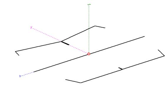 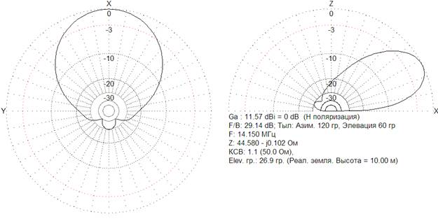 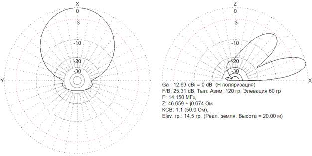 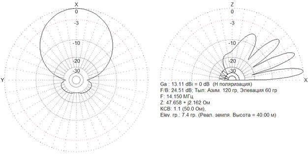 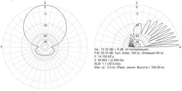 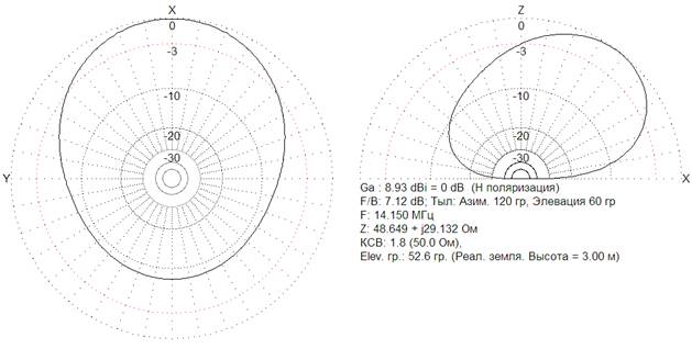 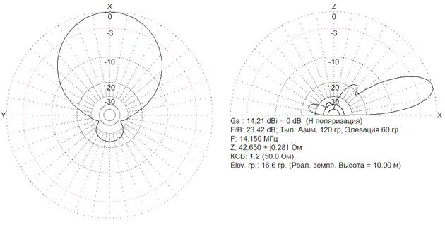 Рис 7 Стек  Рис 8 Стек Владимир Приходько EW8AU | |
| Просмотров: 2099 | Рейтинг: 0.0/0 |
| Всего комментариев: 0 | |